Stair Features
AECOsim Building Designer stairs can be configured to a multitude of sizes, shapes and layouts. The following describe several placement assisting features of AECOsim Building Designer stairs.
Stair Configurations
Stairs are provided with frequently used industry standard stair configurations for placement.
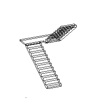
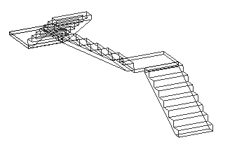
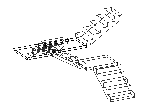
Straight Run - A floor to floor straight run. It is a default stair assembly requiring two points; one to define the flight origin, and another to define the direction. The origin is the anchor point as set in the Stair alignment and the mouse maneuvering determines the direction of the run. Two Straight Run - An assembly of two straight run stairs connected with an intermediate landing. In this case the second point, the landing point, determines the position of the landing; where additionally rolling over of the mouse manipulates the treads distribution in the runs. Quarter Turn - In case of quarter turn stair configuration, followed by the flight origin it additionally accepts the landing point. The landing point decides the place of landing and distributes the treads in the segments. For stair with even number of risers the starting and end segments will have equal distribution of risers whereas for the stair with odd number of risers the starting segment will have one riser more than the ending segment. The next data point is the direction point. The cursor movement determines the angle and the distance the cursor is away from the flight origin determines the tread distribution. You can also lock a desired angle in AccuDraw. In the quarter turn the cursor movement can orient the segment in 180 degrees in the X–Y plane. The landing depth is typically set to the stair width (W), plus one tread (T). However, it can be modified (increased) using the Heads Up Display dimension editor. Half Turn - The half turn stair configuration resembles to that of quarter turn, except the direction point controls the landing width keeping the segment orientation unaltered. The landing point determines the place of landing and distributes the treads accordingly in each segment. Moving the mouse away from the origin in the response to the direction point flips the segment in either direction. This orientation determines the direction of travel of the legs of the stairs in clockwise or counterclockwise direction. The default distance between two segments is set equal to the tread depth (T). Extending the cursor beyond 2W+T stretches the landing width. Two Quarter Turn - The two quarter and three quarter stair configurations are more flexible to place. These assemblies equip with two and three default landings respectively. The first point is the flight origin. The successive landing points determine the location of the landing and also do the tread distribution. Followed by it the direction points determine the rotation of the rest of the stair segments within 180 degree. The dynamic behavior of the segments follows same as that of the quarter turn stair. The two quarter turn stair is constructed with two sets of landing and direction points and the three quarter turn with three such sets of data points. Three Quarter Turn - The quarter turn, 2- and 3- quarter turn stairs can be manipulated the landing dynamically when setting the direction in 180 degrees. While doing so, the exterior length of the landing is maintained at the dimension of stair width (W).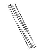


Stair Alignments
The predefined configurations of stairs can be aligned to a suitable side with the help of the controlling anchor point (red dot) for placement.
 Left Base
|
 Center Base
|
 Right Base
|
 Left Landing
|
 Center Landing
|
 Right Landing
|
 Left Top
|
 Center Top
|
 Right Top
|
The alignment option aids aligning the stair assembly with the existing architecture. The base is the bottom of the stairs with the direction of travel going up. Similarly, top is at the top of the flight of the stairs with direction of travel going down. Center stair alignment uses the walk line for placement.


For stairs other than straight runs, the alignment with landing defines the first point for the intermediate platform, followed by the landing point. While setting the landing point the treads are distributed. The first segment defines the starting (base) stair segment and goes in a direction of travel of down from the landing and the second segment defines the ending (top) stair segment that goes in a direction of travel of up from the landing.
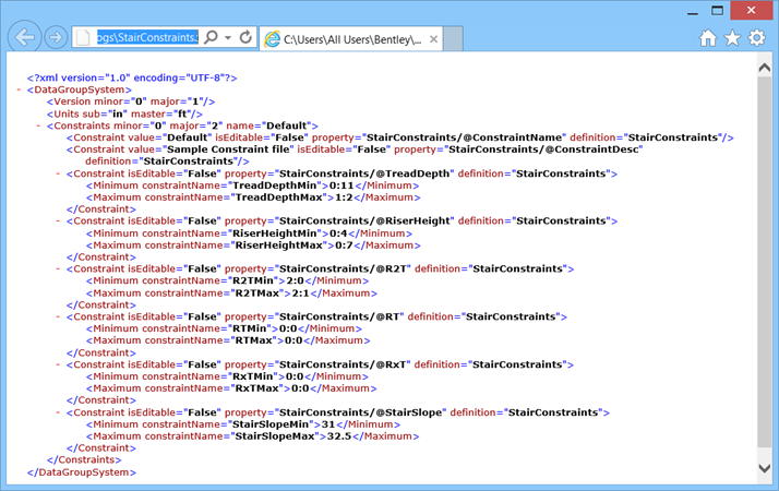
Constraints
The standard stair types inherit predefined properties. The boundary limits on the stair dimension and geometry are governed through a set of constraint rules defined in an XML file. When validation is set ON, the stair placement function always checks with the constraint limits and warns when stair assembly deviates from the values set in the constraint system. Designer gets a quick clue on resetting the or tuning the value in a safer limit to avoid stair with vague specifications.
Placing a stair outside the constraints prompts typical warnings messages.

The alert messages also list the safe limits set in the currently active constraints definition.
| Alert | Recommendations |
|---|---|
| Stair Design is not within the constraint limits. | |
| TreadDepth
RiserHeight |
Check Tread Depth
Check Riser Height |
| Riser Actual Height exceeds the Riser Target height. | Adjust Riser Actual No. |
| TreadDepth is below/above the Minimum/Maximum Constraint limit of 1:0/1:5. | Set the TreadDepth in Treads panel within 1:0–1:5. |
| Riser Height is below/above the Minimum/Maximum Constraint limit of 0:4/0:7. | Set the Riser height in Risers panel within 0:4–0:7. |
| The combination of Riser Height and Tread Depth do not accommodate the 2(R)+T, is below/above the Minimum/Maximum Constraint limit of 2:0/2:1 | Alter the Riser Height or Tread depth to set the 2R+T value within 2:0–2:1. |
| The combination of Riser Height and Tread Depth do not accommodate the R x T, is below/above the Minimum/Maximum Constraint limit of 6:3/6:4 | Alter the Riser Height or Tread depth to set the RxT value within 6:3–6:4. |
| The combination of Riser Height and Tread Depth do not accommodate the R + T, is below/above the Minimum/Maximum Constraint limit of 1:5/1:6 | Alter the Riser Height or Tread depth to set the R+T value within 1:5–1:6. |
| Stair Actual Slope is below/above the Minimum/Maximum Constraint limit of 31.00/32.00 | On the ribbon bar adjust Stair Height or in the Placement panel manipulate either Tread Depth or Riser Height (target height) properties or change Riser Actual Number to fit the geometry within the allowed elevation. |
| There is no active floor defined or floor to floor distance is zero. | Activate a valid floor in the Floor Selector. |
The alert messages would indicate Max Constraint limit when values cross higher limits set in the constraints definition.
Match Stair
Selecting The
 Match Element
Properties option on the Place Stair properties dialog allows you
to place stairs matching the stair attributes with one that already exists.
Match Element
Properties option on the Place Stair properties dialog allows you
to place stairs matching the stair attributes with one that already exists.
allows you to set current active
settings to match the parameters of existing stairs in the open model saving
time when placing matching stairs in a model.